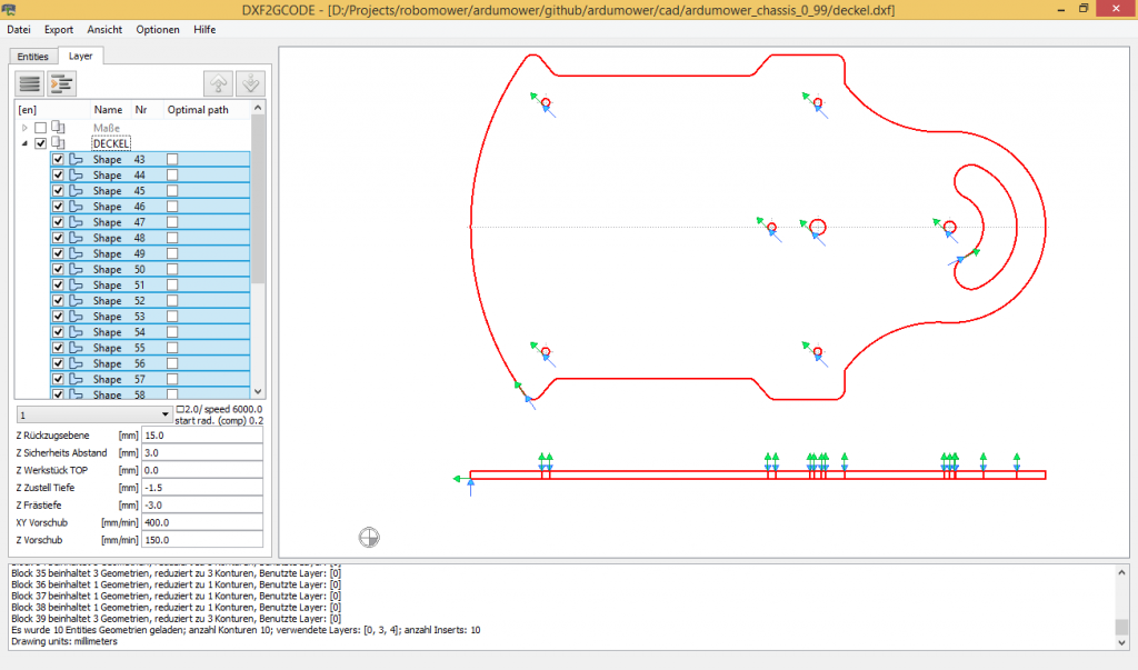


AuthorĬontributions, issues and feature requests are welcome!įeel free to check issues page. Properties S and F are exposed in path settings in UI. G2 X where # is one of the supported variables and n the float precision: Name Simple set of GCode command is used per tool: Description tools with settings such as radius and gcode formatting.Within this app, open your DXF file Select/deselect all layers in the left. general settings aiming dxf importing or default values Step 1: Generate the G-Code from your DXF files Download and extract DXF2GCODE.Once opened, select path from left panel or from viewport and modify settings of selected path group or of single selected path.Įxport with File->Export or Ctrl+E ✏ ConfigurationĬonfiguration settings are exposed in Configuration->Settings, the configuration is splitted in two: I consent to receive emails about the requested product.Build$. We provide examples in the following languages: C#, Delphi, C++Builder, Visual Basic, Visual C++, ASP.NET and VB.NET. If you need a library for developers with G-code generation feature, please write to us at or fill in the form below. See more detailed information on licensing options and prices on the ordering page. The price of one user license starts from 73 USD. The file will be saved with the NC extension.

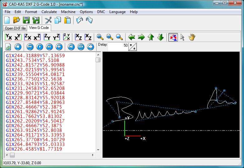
To save the generated G-code click the Save G-code button. Secondly, I have a laser cutter that accepts Gcode and wanted to optimise the conversion of DXF files to Gcode by changing a adding/changing three things.You can change a machine type in the G-code settings window on the General tab. Please note that by default ABViewer generates G-code for a milling machine. You can find more information about it here. In the opened G-code window configure all necessary settings.On the Output tab select the CAD to G-code command.If you need to edit it, use the tools on the Editor tab.


 0 kommentar(er)
